


Building a Killer Home Wi-Fi Solution with Ubiquiti UniFi : Part 2
Introduction
This is a post about home Wi-Fi. Specifically, my home Wi-Fi. About a year ago I moved house. Ever since then Iâve wanted to up my game when it came to wireless internet provision at home. I work from home a fair bit. Iâm also a keen Smart Automation hobbyist and I firmly believe that over the next 10 years the number of Wi-Fi-connected things weâll own is only going to go up. Itâs important that there is a solid base for all these devices to operate on if theyâre not to cause endless tiny and annoying problems. Itâs also important (to me) that I can monitor whatâs going on, whatâs connecting to what, and be able to control it.
In part 1, written just over 6 months ago, I covered my initial installation: Security Gateway, a switch, some APs and a Cloud Key. In this second half, I’m going to cover the additional work to complete my home setup.
for your information: after I wrote my Part 1 blog post, Ubiquiti reached out and wanted to say thank you by sending me some bits and pieces. Some of these feature below.
Choosing Ubiquiti UniFi
Clearly, I’m already pretty invested in UniFi equipment, but it’s worth pointing out that since my last post there haven’t really been any stand-out competitors in the Wi-Fi mesh space, and I’m still very happy with my choice.
Since my last post, though, Ubiquiti has launched another Wi-Fi mesh product, AmpliFi.
Focused squarely at consumers who want a mesh solution that Just Works, without configuration or tweaking, this takes the power and knowledge Ubiquiti have from producing enterprise-grade Wi-Fi solutions and packages it up into simple components: a box, mesh points, and a mobile app. For me, I don’t think I’d be happy being completely hands-off, but this is definitely something I’d recommend to friends and family looking for a friendly but powerful mesh replacement. That’s all I’m going to say about it though because I’ve not used it myself.
Plan 1 Recap
As we left things at the end of my last post, this was how things looked:
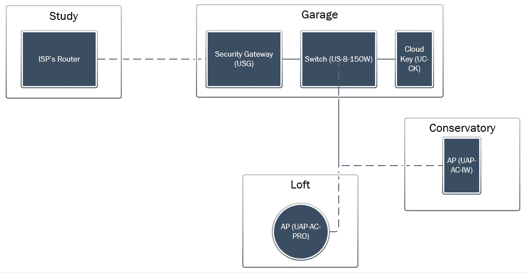
This setup gave me 5Ghz everywhere upstairs and in the conservatory, and a mixture of 2.4 and 5 everywhere else. Whilst I was getting great WiFi coverage with this setup, there were a couple things I wanted to improve:
- I wanted to add more APs downstairs to provide 5Ghz everywhere
- I knew that the ISP entry point was going to change from one side of the house the other, which would change the routing of some of the cables.
Since then, I’ve added some more requirements:
- Better coverage outside at the front of the house. There are two reasons for this. The first is so that there aren’t any dead-spots when working outside, or when moving from the cars to the house. (It’s actually surprisingly annoying to be walking to/from the car, trying to turn off the lights or adjust the temperature and have everything freeze because the phone is transitioning between Wi-Fi and 4G.
- More network points in the living room, where the TV is. For streaming media, wired is still the best experience, and I wanted to be future-proof for Smart TVs, games consoles, streaming boxes etc.
I was expecting by now that Virgin Media would have finished their installation of cable to our village, but that still hasn’t happened so the ISP route into the house is still in the same place. However, it’s imminent, so I wanted to make sure I was ready for when it happened.
Planning it out
Getting more APs downstairs was going to involve getting cable to some tricky places. When I did Part 1, which involved running a cable from the Study (where the ISP entry point is) to the garage (where the Security Gateway is), I ran a few more cables (which are all hidden behind kitchen units and through walls) – so I could easily place an AP there.
The other place I wanted to put an AP was in the living room. This was harder, it’s the other side of the house. The other problem was that when the ISP entry point is changed, it will move to be here as well (cable tends to come in by the TV, which makes sense). Getting the internet feed routed back to the garage was going to be hard, but I didn’t want to put all the networking equipment in the living room. Likewise, having the switch in the garage made sense for the APs on that side of the house.
I thought the easiest way of running cable from one side of the house the other was to go into the loft. Remember, from Part 1, I’m already running a cable from the garage to the loft for the loft AP. My plan was to run a cable from the living room, through the loft and down to the garage. This cable will be the “master cable”, from the ISP router behind the TV and to the Security Gateway.
Then, I planned to install a switch in the garage, re-using the original cable from the garage to Loft AP, and then run some additional cables from the switch in the loft to the living room (more on this later), to the Loft AP, and also to an outside AP.
Here’s what that looks like as a rough plan:
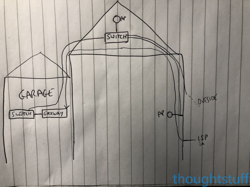
If it looks confusing, it is! I’m running a cable from the ISP router all the way through the loft and over to the garage, only to have another cable come all the way back to the loft, and then another one back from there to the living room, for an AP that will be sitting right next to the router! However, doing it like this means that all the traffic is protected by the Security Gateway and gives me maximum flexibility in the future.
If you’re doing anything other than the most simple setup, it’s definitely worth planning out where everything is going to go first on paper. It gives you a chance to count how many switch ports you’re going to need and highlights tricky cable runs which you’ll have to manage. After several attempts, this was the final plan, combining what’s already installed from part 1 into a complete solution. You’ll notice I’ve added another switch (a 16-port UniFi POE one) to the setup, replacing the 8-port one that was in the garage, and moving the 8-port one into the loft:
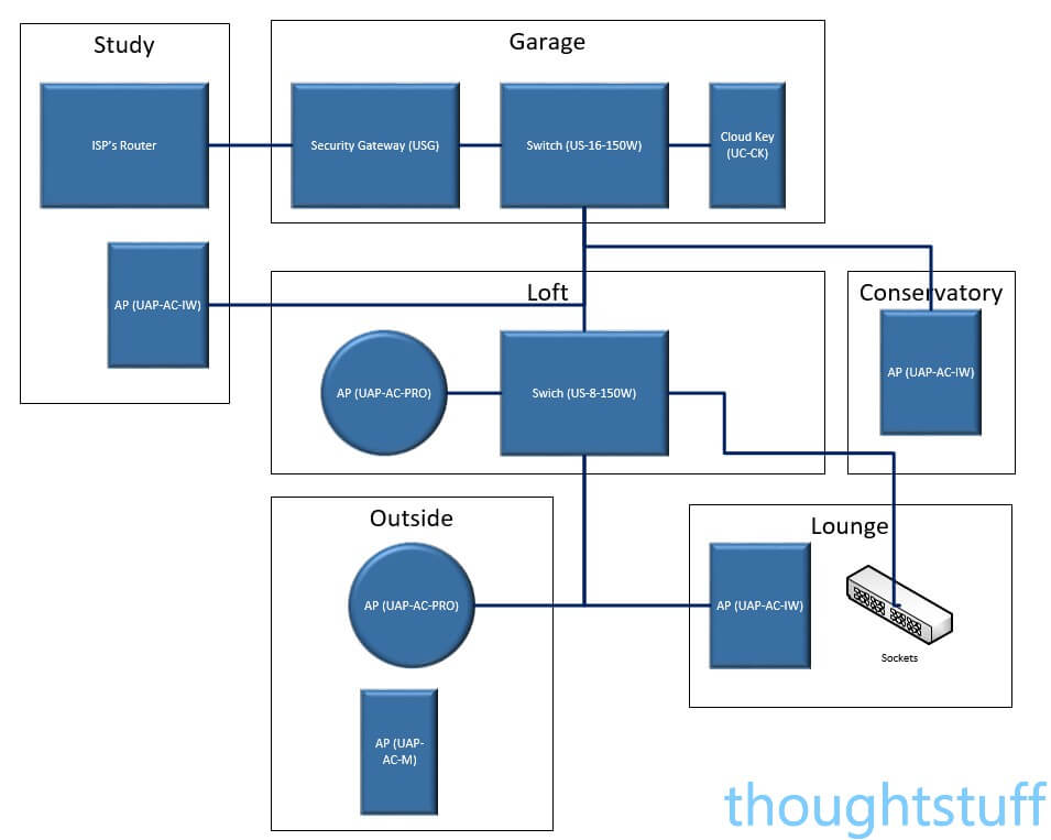
One aside: you’ll see from this diagram that there’s a lot of equipment planned to be in both the garage and loft. Whether that’s a good place for it is largely down to your point of view, and the temperature ranges of where you live. For me, I was happy that the temperatures which both those locations would expect to see fall within the operating range of all the equipment, and that it was a worthwhile trade-off to not have all that kit indoors. However, your evaluation might be different depending on your circumstances.
Running the Cable
I already had a cable running from the garage to the loft, so that was no problem. However, I now had a requirement to run a number of cables from the loft to the living room, and outside. You’ll remember from Part 1 that I don’t like cables being visible. Once I counted up what I needed, including redundancy I ended up with 4 cables to run from loft to living room for a 4-way patch panel (one of which would be the ‘master cable’ and go on to the garage), another cable from loft to living room for an AP, and 3 cables from loft to outside (1 AP, 1 camera, 1 redundant). 8 cables. For someone that doesn’t like visible cables, fixing 8 cables vertically up the side of the house wasn’t an option!
I thought about attaching a drainpipe vertically to the side of the house to enclose the cables, but I just couldn’t work out a good way of running the cable from the drainpipe into the house nicely and in a weather-proof fashion. In addition, I was a bit worried about what it might look like to have a drainpipe on the side of the house that didn’t actually go anywhere.
There was one other option that I’d initially discounted but gradually came back to give some serious thought to. Could I run the cable within the walls from the loft straight down to where I wanted them in the living room?
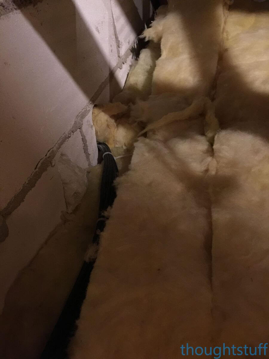
In the UK, a house built in the 1980’s has a wall structure that looks like (working outside in): brick, airspace, blockwork, plaster. To make things fun, the airspace in our house had been insulated with thousands of tiny insulating balls which are “blown” in through holes drilled in the brickwork and then plugged up. Various other protrusions, waste bricks, metal tie-rods, electrical cable etc mean that trying to run cable here is something of an obstacle course.
It took me a solid 3 days of drilling, messing around, trying different approaches and making numerous trips between the two floors: but I finally managed it. The combination of tools which worked for me (and your mileage may vary here) were:
- a big drill bit!
- a set of rods (like these) – I used these to poke my way through the insulation, navigate the protrusions. Half the rods are still in there because they got snagged on something and broke off
- a boroscope (like this) – which actually wasn’t that useful because of the insulation, but helped in the final stages because I had to “go fishing” for the rod from the living room horizontally and this helped me find it
- a Tile Mate – yes, I got that desperate that I duct-taped a Tile Mate onto the end of the rod and played its noise to try and figure out where in the wall it was
(If you can think of a better way of doing this, thank you, but I’m done now so don’t need your advice :). It’s worth noting I even hired a ‘professional’ to come and do this who tried for 6 hours and gave up.) I can’t honestly recommend this approach to everyone, but if you really don’t like wires and like a challenge, at least you know it’s possible 🙂
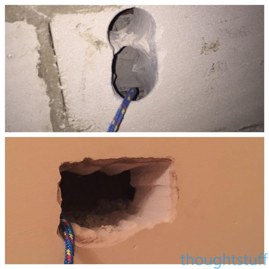
Some photos for you. Here are the two holes – the top one is in the loft (see how many holes I had to drill to get the angle right for the rods), and the bottom one is in the lounge (luckily I’d already decided on a double-socket to hold 4 network points, so it wasn’t a big deal to make such a large hole – this really helped with “fishing” for the rod when it didn’t come down straight. Notice the rope – as soon as you’ve pushed a rod down and found it at the other end, attach it to some rope and pull it up, and then use the rope to help with pulling the network cables through, pulling the rope alternatly up and down. When you’ve finished, leave the rope in in case you need to do it again in the future – it’s totally worth the money spent on the rope!
Here’s what it looked like once all the cables were pulled through. You can see the 8 network cables runing towards the bottom-left of the picture to the cabinet:
Remember I said earlier that I wanted to run 3 cables outside for an AP, camera and 1 more for the future. Once I had the rope in place, it was relatively easy to drill an access hole through the external wall where the rope comes down (I actually did this through the double socket opening) and run network cable through that:
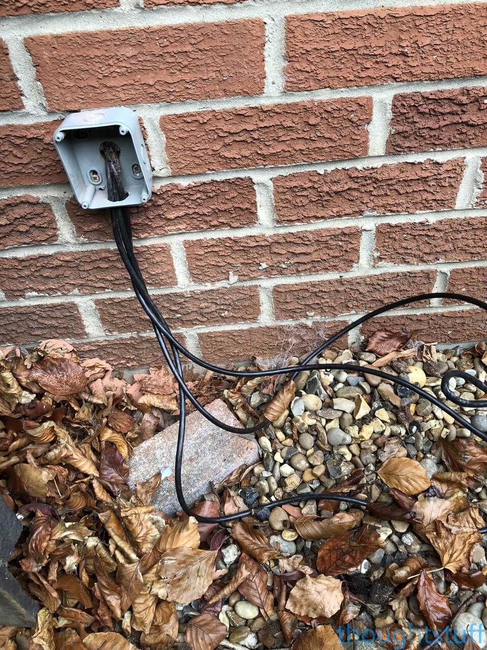
I’m using direct-burial network cable, which I then dug a trench for, surrounded with some trunking (less to protect, more to make it more manageable to work with than 3 separate strands) and hid away.
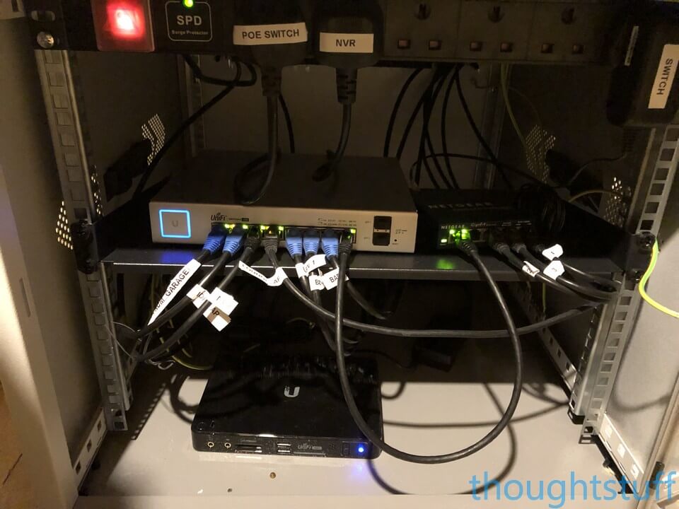
I setup a small networking cabinet in the loft for the switch. There’s a UniFi POE 8-port switch which provides POE to the Lounge AP, the outside APs, the Loft AP and has the uplink from the Garage, plus another non-powered switch to for the network points in the Lounge. I’ve also put the UniFi Video NVR there as well (see my blog post on building a killer Home Security Camera System) to keep it out of the way. Here’s what the inside of that cabinet looks like:
Adding in the APs
Right, that’s the boring hard work done! The next part is more interesting and fun – adding in the APs.
In order to achieve my aim of 5Ghz everywhere downstairs, I decided to use more In-Wall APs. I previously mounted one in the conservatory (in part 1) and was impressed by not only how well it worked, but how good it looked. The plan was to put one in the living room and one in the study. In addition, to future-proof the project, I would add 4 network sockets behind the TV.
Mounting a UniFi In-Wall Access Point in pictures
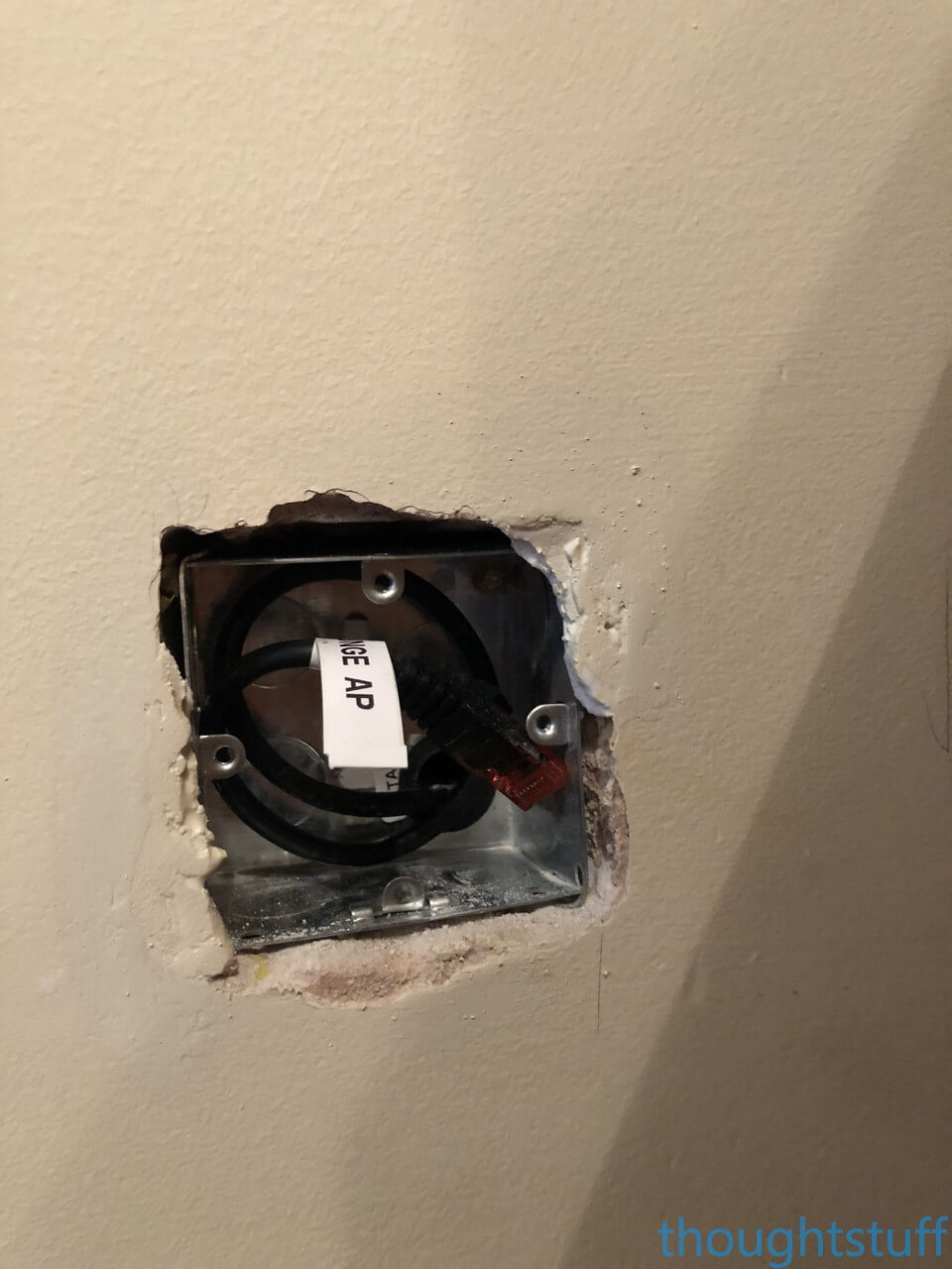
I managed to remember to take some photos whilst mounting the AP in the lounge. I started with a UK-style pattress box. The AP comes with a universal mount: if you’re unsure whether or not it will fit your country’s system I produced a template you can download to check.
Start with a back-box in place and a network cable:
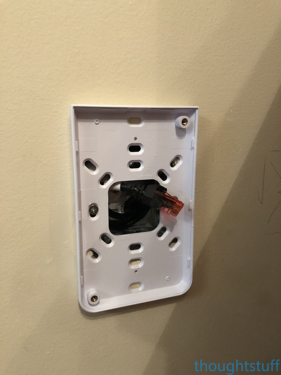
Fit the template to the back-box using the screws provided:
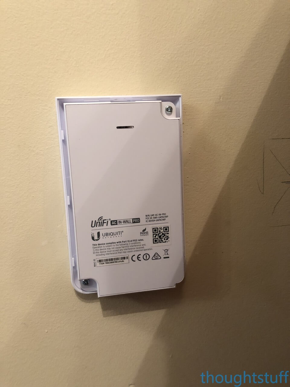
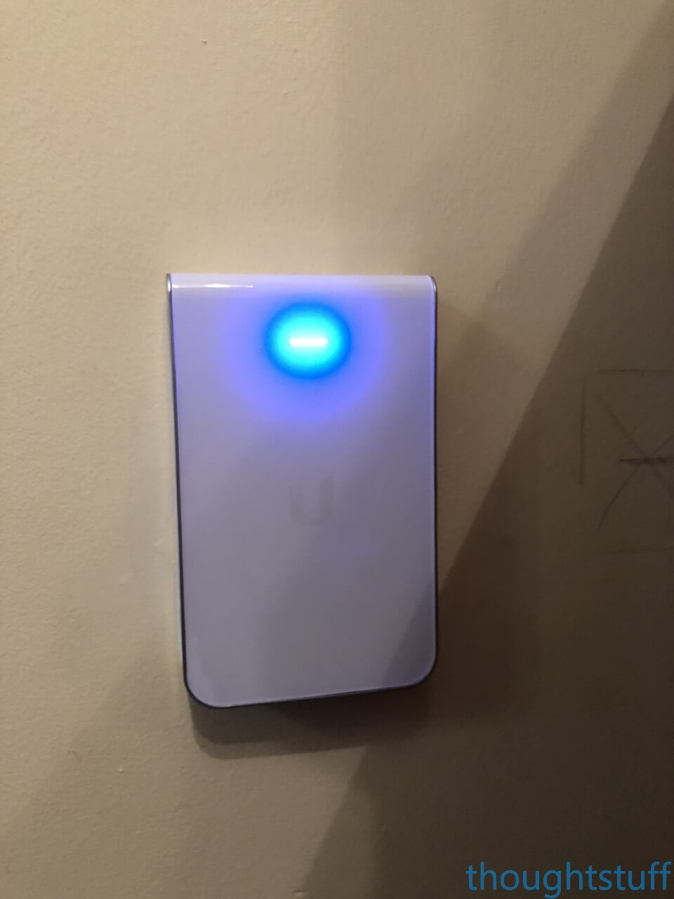
Plug in the AP and screw it onto the mount:
Clip on the cover:
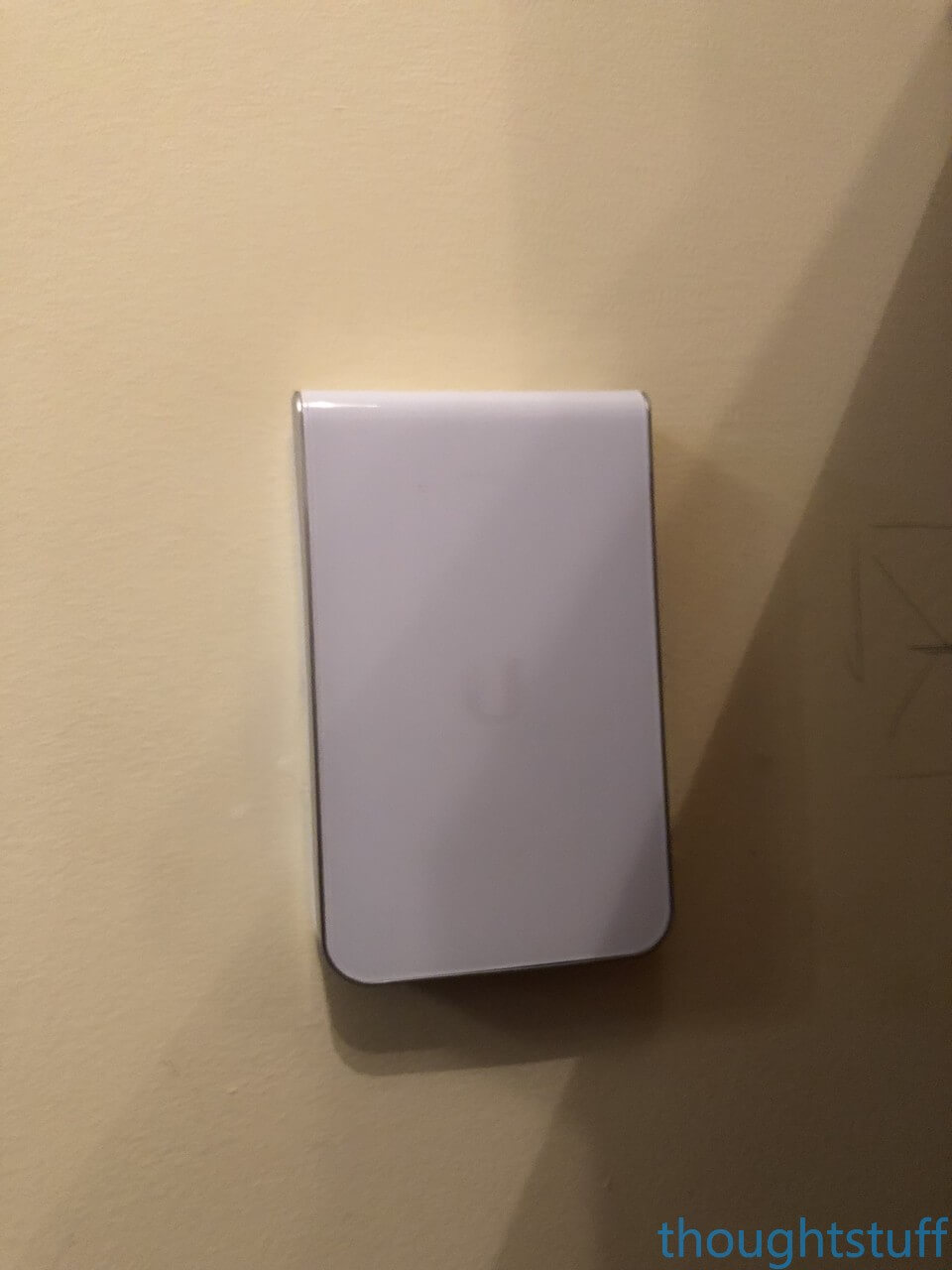
Connect to the UniFi system to turn the LED blue!
Here’s what the lounge looks like now, behind the TV. There are the 4 network sockets (yes, needs decorating etc – but it’s hidden behind the TV) and the AP.
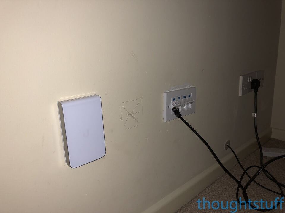
Fun fact: 3 of the network sockets go to the switch in the loft (as you’d expect). The other one actually goes into the loft but then keeps on going all the way over to the garage and into the garage switch. The reason is that if we ever change ISPs and the internet comes in here (lots of cable providers bring everything in behind the TV) then I have a line from the ISP’s router directly to the security gateway. Future proof! (hopefully).
Study
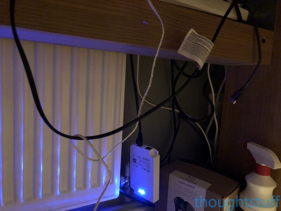
The AP in the study still needs to be properly attached to the wall. At the moment there isn’t a back-box for it to attach to, so it’s currently just dangling under the desk. It’s on the to-do list to fix, but for now it still works great, as you can see:
Outside
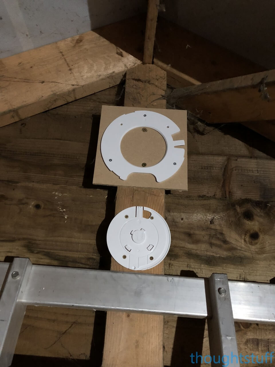
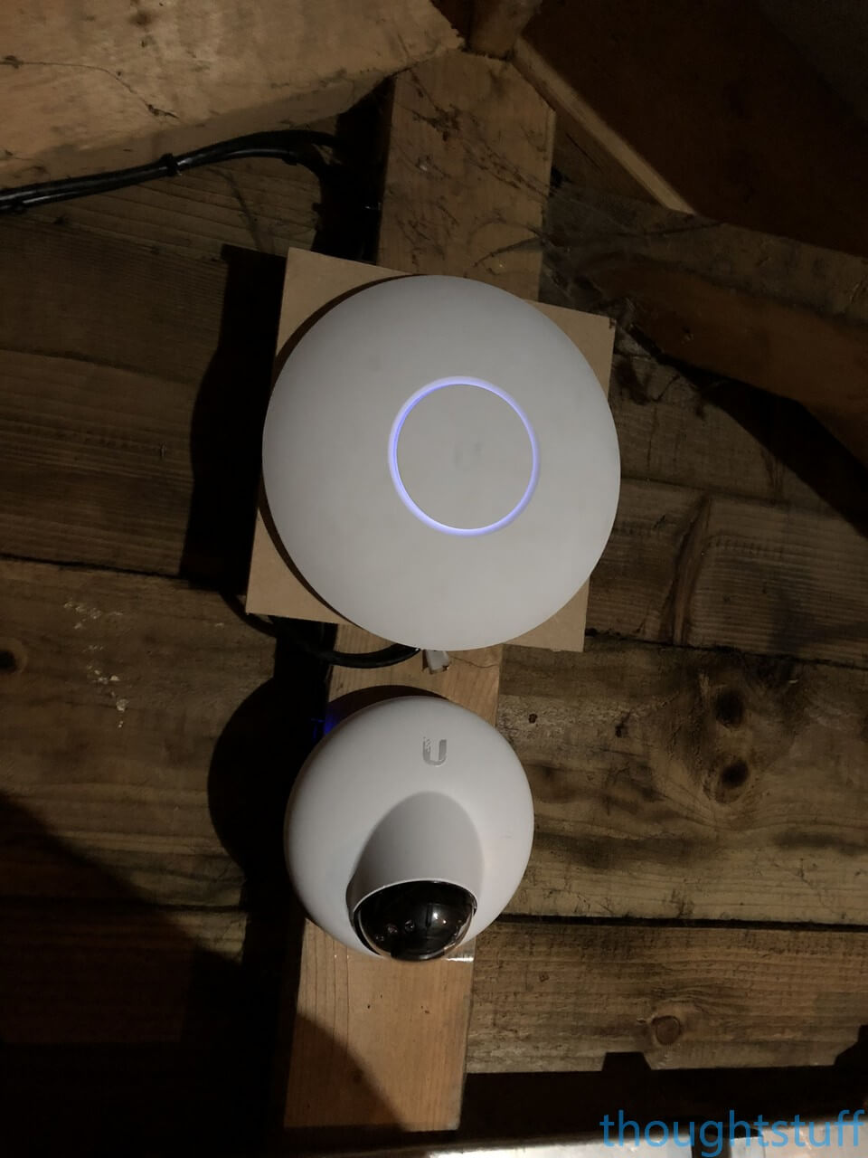
Outside, I used one of those 3 network cables for a UAP-AC-PRO AP (see my unboxing and walkthrough video) and another one for a G3-DOME (see my unboxing and walkthrough video) – both of which are only suitable for mounting outdoors if they’re protected, such as here (top photo is just the mounts):
5 Ghz everywhere!
One of the major advantages of the UniFi system is that you can add as many APs as you can cable in. At some point though, you have to start thinking about how those APs are going to work with each other, and guard against them fighting for the same radio space.
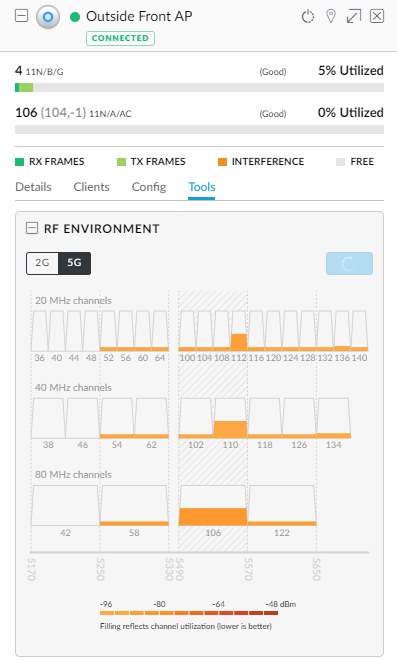
Each UniFi AP can be manually configured to adjust the channel and strength of the signal. The first thing I did was manually set all the APs onto different 5 Ghz channels. Each AP can be set to perform a 5 minute RF scan, which monitors the spectrum to show you which channels are most used where that AP is sited. This lets you very accurately choose channels for each AP which don’t interfere with each other, or with neighboring networks:
Secondly, I used Acrylic Wi-Fi Home to track the strength of each AP. I wanted the In-Wall APs to provide enough power for the room they were in, but not so much that there would be interference/confusion for devices with the other APs. For me, I found that setting the transmit power to Medium gave me the best results. I moved from room to room, using Acrylic to make sure that as I moved out of one room and into another, the relative strength of the AP in each room changed, so that devices in a room would also settle on using the AP for that room.
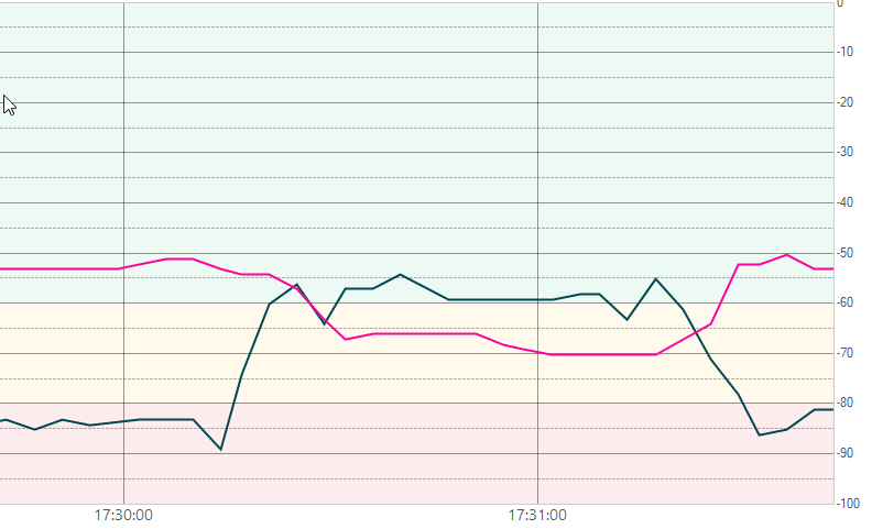
This is a graph output from Acrylic. The pink line is an In-Wall AP in the Study, and the Green line is an In-Wall AP in the Conservatory. I just picked up my laptop and walked from the study to the conservatory and back. The distance I walked between rooms was maybe 6 meters, 3 meters as the crow flies. (the APs are probably about 3 meters apart). You can see though, how the signal from one drops as the signal from the other jumps. This is what I was looking for because this way users will be spread out between APs and devices will be a close as they can to an AP giving greatest throughput.
The third thing I did was to turn off the 2.4Ghz radio on all APs apart from the one in the Loft. Why? Well, my preference is for devices to use 5Ghz where they can. However, many devices are stupid and will use the radio signal which is strongest, without taking anything else into account. What that means is that given an AP that’s pumping out 2.4 and 5, a device will often end up on 2.4. For me (and your mileage may vary), I found that having one AP providing 2.4 covered the whole house well enough for any devices which need it but gave a lower signal than the local APs in the rooms, meaning that 5Ghz-capable devices always used the local 5Ghz. It works for me, it might not work for you – but it may be worth a try.
UniFi Dashboard
I’ve written about the UniFi software before. This is where you configure all aspects of your WiFi, and I spent a lot of time here tweaking and trying things out. The software is very forgiving, it’s pretty hard to really mess anything up too badly (even for a n00b like me!), but it’s powerful enough to do all the things I’ve already mentioned, like changing transmit power, turning radios off etc.
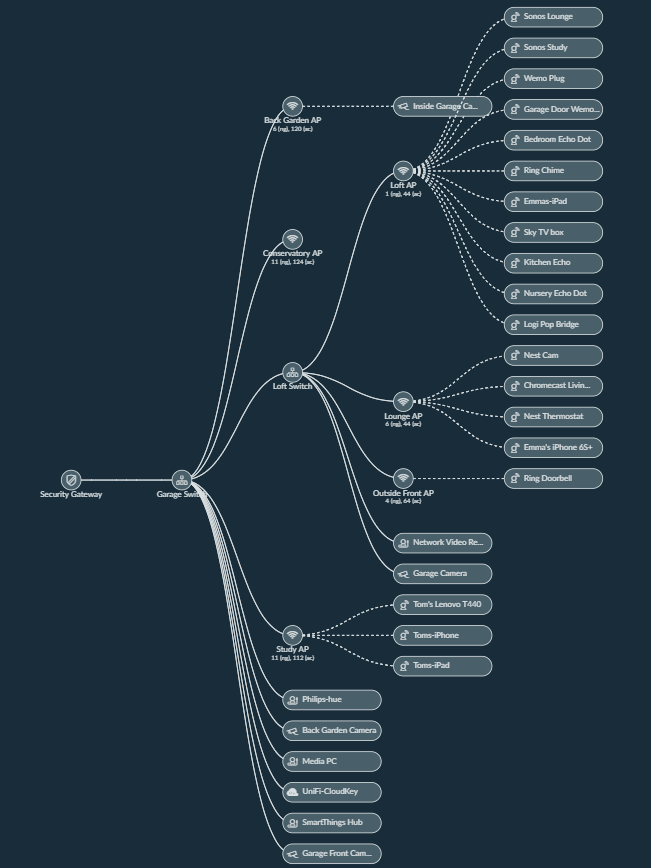
It also has some nice visualisation features, such as this ‘map’ of the network:
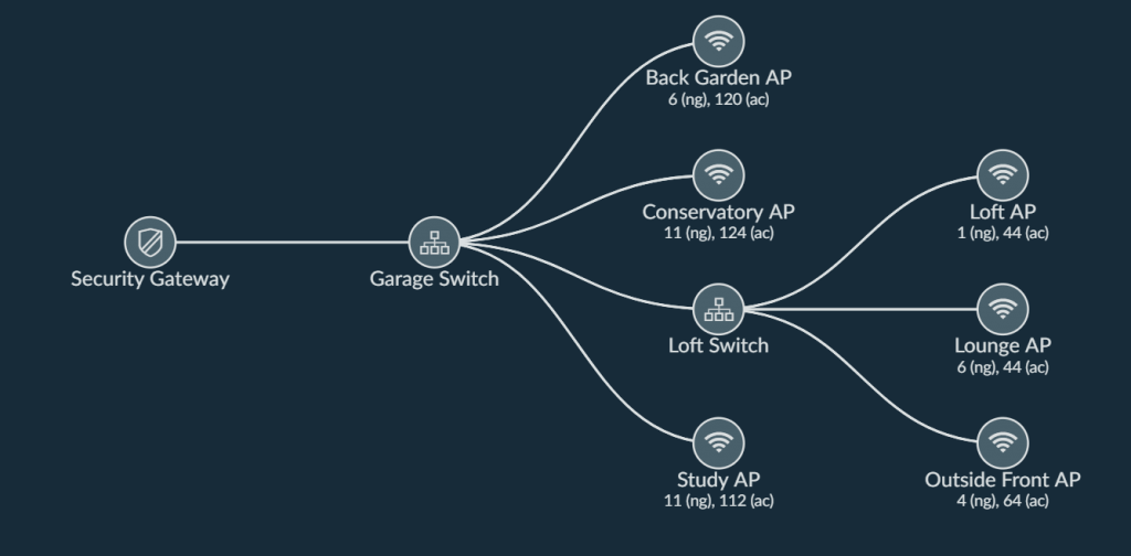
You can also view it with the connected clients, which can be useful for identifying which APs are being used the most:
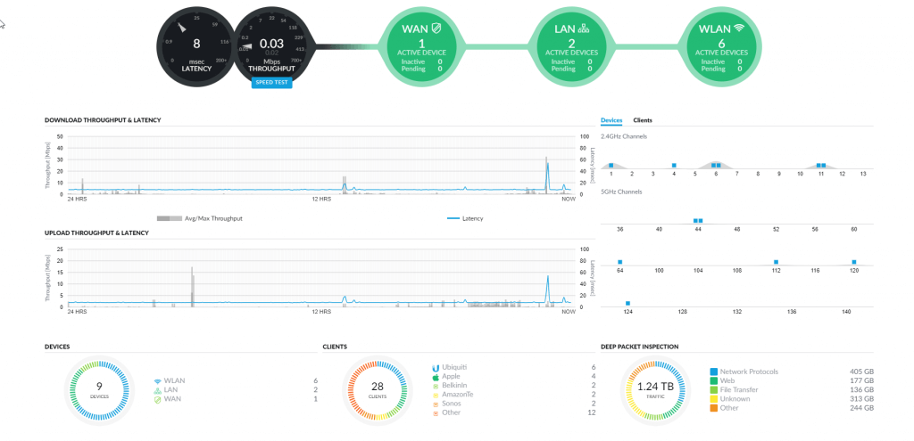
I already talked about some of the features of the Dashboard in Part 1 so I won’t repeat myself other than to show you what the Dashboard page looks like now:
One thing that’s new though is that you can now use the mobile app to perform a real-time throughput test & build out a heat-map layered on top of a plan:
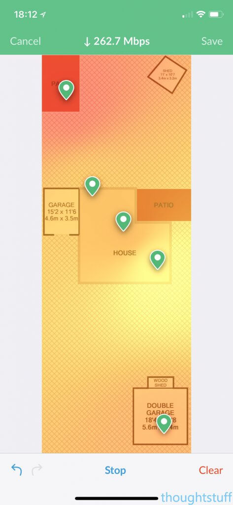
This is really useful, both for finding dead-spots, but also for making sure that your WiFi is as good as it can be in the places you spend the most time. The speed metric at the top changes in real-time, so you can move from room to room, doing tests and dropping pins to build out the heat map.
Conclusion
It’s been nearly a year since I switched over to Ubiquiti. I’ve been very happy with them. Clearly, my house is now over-provisioned for WiFi, but I’m OK with that! I’ve stopped worrying about signal now, wherever I am in the house. I know that I’m getting the most from what I pay my ISP for internet and that when we switch to faster internet speeds, the WiFi won’t be the bottle-neck. Friends love the guest portal, and I like that I can offer them fast WiFi without worrying that they’re going to muck up my smart home. I’ve stopped worrying about WiFi – it’s as dependable as the water supply, but it’s also something that’s fun to tinker with when I have the time.
Simple things make every day easier – perfect WiFi even once you’ve got into the car that’s on the drive means that planning routes works faster and quicker. WiFi in the garden means that working from home in the summer is a much more pleasant experience. And my favourite weekend hobby of pottering around the house and garden doing odd jobs listening to Tune In can happen without the cut-outs and buffering I used to get.
Great WiFi really is a game changer, and it’s been fun process to go through to get.
Related posts:
 Building a Killer Home Wi-Fi Solution with Ubiquiti UniFi
Ubiquiti UniFi Switch 16 150W: first look and setup
Ubiquiti UniFi Switch8 150W: first look
Building a Killer Home Security Camera setup with the Ubiquiti UniFi Video System – First Look, Setup & Configuration
Ubiquiti UniFi AC In-Wall Pro: first look
Building a Killer Home Wi-Fi Solution with Ubiquiti UniFi
Ubiquiti UniFi Switch 16 150W: first look and setup
Ubiquiti UniFi Switch8 150W: first look
Building a Killer Home Security Camera setup with the Ubiquiti UniFi Video System – First Look, Setup & Configuration
Ubiquiti UniFi AC In-Wall Pro: first look
Tom, would you have bothered with all this now with more mesh WiFi available such as Google, BT, Netgear etc?
Great work Tom on your setup – Am very interested in the InWall Ap’s – would they fit over a back box of say a single TV antenna point? Seeing as I’ve no need for terrestrial TV points or the cables – I was thinking to pull some CAT6 through to 3-4 rooms…
Graham – Mesh’s are not the same as his setup. Having his AP’s (access points) connected & powered by his switches means there is no throughput degradation or increased latency which there would be on a mesh setup, plus data and power is carried over 1 wire. Mesh’s or repeaters require each access point to communicate to each other until it reaches the Mesh point which is connected to the actual router. Plus a number of his cameras, I would expect to be powered over the ethernet from his switches via PoE something Mesh setups don’t offer..
Ubiquiti do offer their AmpliFi mesh setup, for the home user, UniFi’s software/firmware would blow BT’s & Sky’s offering out of the water – seeing as BT’s HomeHub is one of the worst products I’ve ever owned and their firmware upgrade programme is a joke.
Mostly what Andrew said 🙂 A year ago, Google and BT were both offering mesh WiFi, but I wasn’t convinced/impressed enough. Plus, there is always the problem that you’re trading ease of installation against performance. Mesh WiFi is loads better than a single source so it’s better than what most people have, but having wired-in APs is the gold standard, so I think I’d still do that even coming to it today. It’s short-term pain for long-term gain – it’s a complete pain to retro-fit cable to a house, but once it’s done then it’s done forever and you get the benefits every day.
Andrew – the backing plate fits a UK backbox fine, and I’m pretty sure a UK antenna faceplate is the same size. There’s a template you can print out and double check though: https://blog.thoughtstuff.co.uk/2018/02/ubiquiti-unifi-in-wall-mounting-template/
Tom, thank you. Both posts so useful.
I’m wiring a new house up right now and have bought into the AC-PRO so your information is perfectly suited and timed. I am planning to get 2 switches, one for each end of the house. Bit like yours but horizontally spaced instead of vertically.
I see you have chosen to daisy chain your switches, LoftSwitch feeding into GarageSwitch feeding into Security Gateway. Great to know daisy chaining works. Bearing in mind I know diddlysquat about how a switch works…does that create a bottleneck at GarageSwitch? Just trying to understand your set up: as your GarageSwitch and SecurityGateway are in the same location could you have connected LoftSwitch into the security gateway or would that mean you’d have needed to buy a backbone?
Also I note you had great coverage to all rooms upstairs, but less so downstairs. Is that because you have a different wall construction downstairs (maybe blockwork instead of stud?) or because you have chosen the In Wall AP for downstairs? I was going to go all AC-PRO and stick them on the ceilings (yeah sorry, I think they look great, and confess I do have my router on show, but that’s only because the BT master switch is in the lounge…and we’re just messy people)
Thanks to you, I think I actually understand how we’re going to set this all up, so my appreciation to you.
I love these articles and great to see something from the U.K.
I have exactly the same situation as you – Virgin on one side of house and debating garage by running through the loft, of just all in the loft. Iâm debating cloud key gen 2+ and USG in the loft too
But the loft gets very hot in summer. Have you had any issues with your switch in the summer and heat?
Secondly any issues with the dumb switch and the UniFi managed one, or do they all play nicely?
Thank you for an interesting post. I am considering a similar setup at my house.